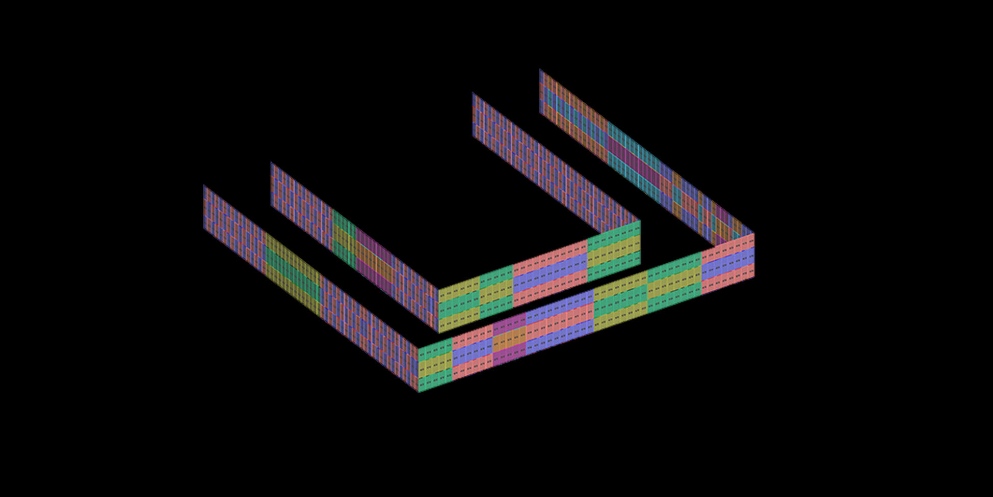
3D Surface Model — Panel Type Colour Map
A scalable Grasshopper framework that transforms 2D facade drawings into a live, data-rich 3D surface model — a single source of truth for design, engineering, quantity analysis, and fabrication across all project teams.
Facade projects involve many stakeholders — architects, engineers, suppliers, fabricators — each working from their own files, drawings, and spreadsheets. Data is scattered, versions conflict, and no single document ever fully agrees with the geometry. When the design changes, the ripple through all those disconnected documents is slow, error-prone, and expensive.
The framework was developed to solve this at its root: one 3D model, driven by the 2D drawings the design team already makes, that all departments read from and contribute to. When the design changes, the model regenerates. The data follows.
The Surface Model Framework is not just a modelling tool — it is a project infrastructure. It establishes a system where the 2D drawings produced by the design department become the direct input to a live 3D model, which then feeds data to every other part of the project workflow.
First deployed on a large-scale facade project at Priedemann currently under construction, and built from the start to be scalable — the template adapts to any project with minimal reconfiguration.
| Department | What the framework gives them |
|---|---|
| 2D Design | Their drawings are the input — no extra step, no duplicate work |
| 3D Modelling | Automated surface model — no manual rebuild when design changes |
| Engineering | Flagged problem areas, live panel data for structural review |
| Procurement | Accurate quantities and type breakdown for material orders |
| Fabrication | Structured data export — a reliable basis for fabrication systems |
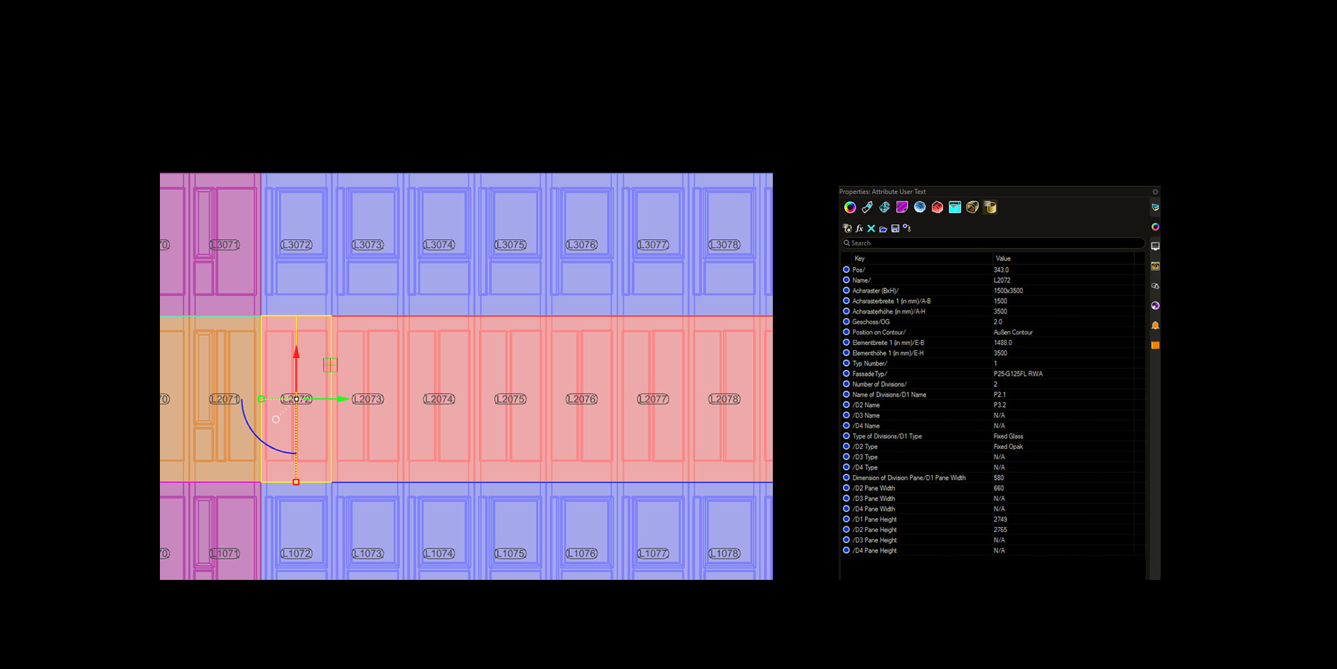
The tool reads a 2D floor plan drawn following agreed-upon drawing conventions. Each curve carries attributes — panel type, floor level, system — that the Grasshopper definition reads and uses to generate the corresponding 3D surface geometry automatically.
Each generated surface panel holds embedded data: type identity, dimensions, position, floor level, and any manually imported attributes. As the design evolves and the 2D drawing is updated, the tool regenerates the entire model — keeping 3D and 2D in sync without manual rebuilding.
The exported Excel file becomes the fabrication data sheet: one document with every panel, its type, its dimensions, and its quantities — ready for material orders, fabrication, and engineering review.

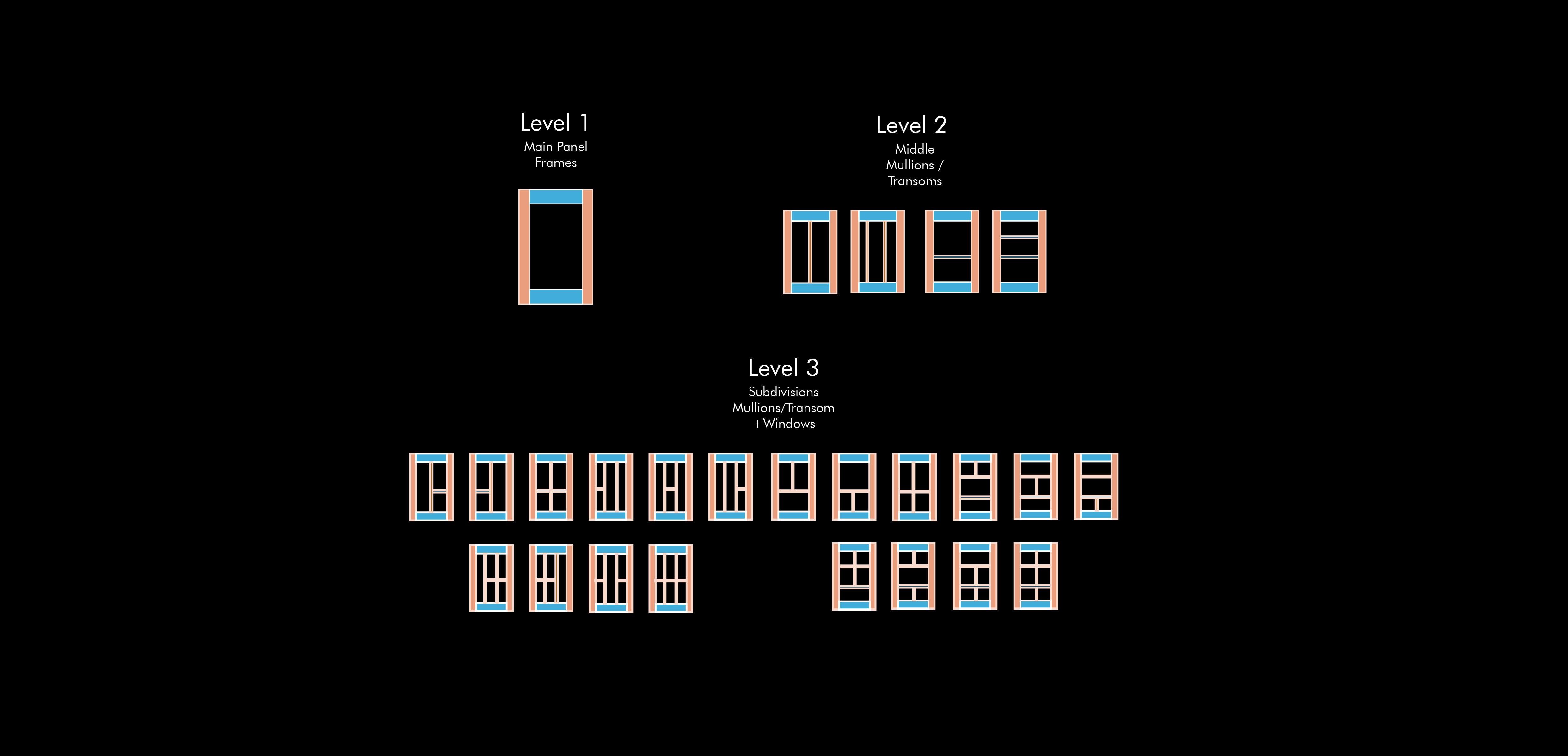
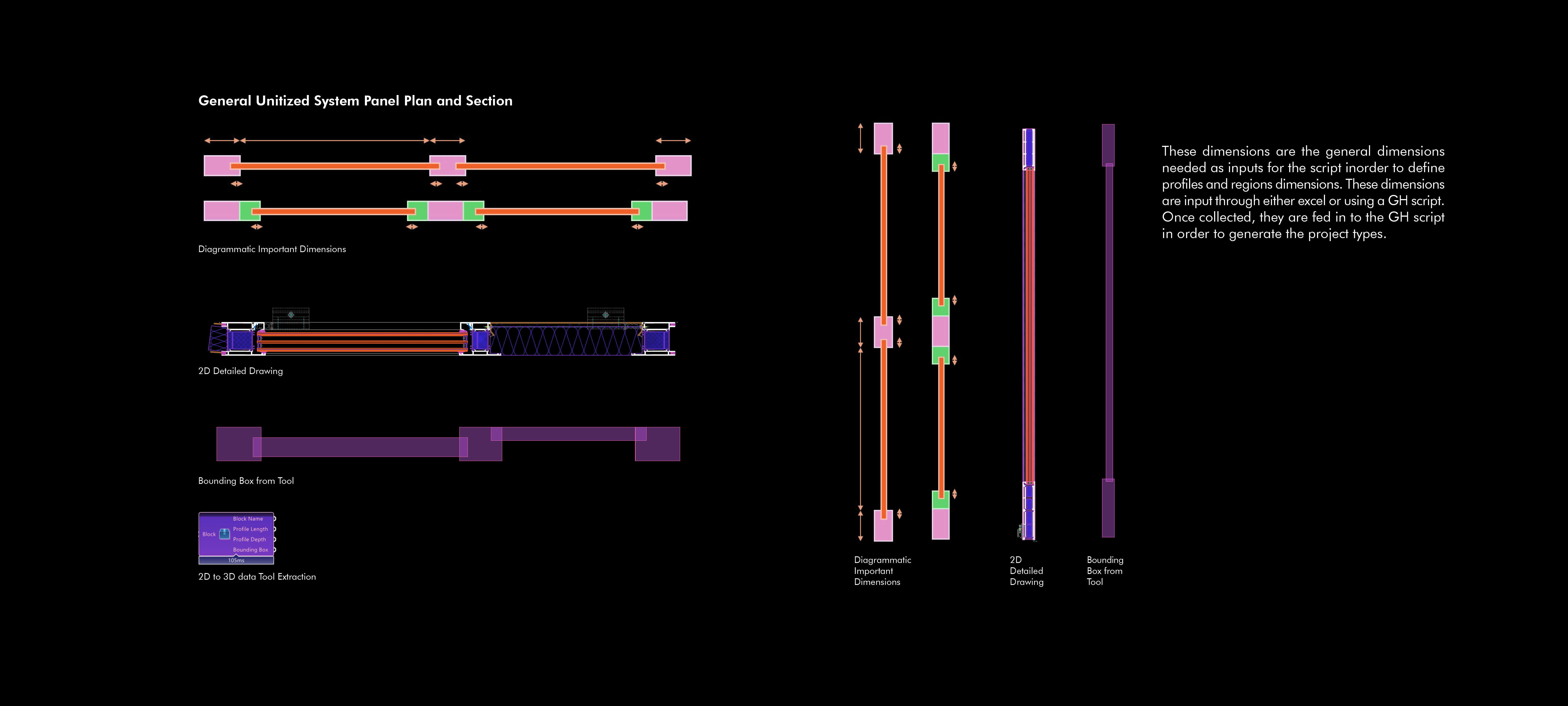
For a typical curtain wall project, each panel type requires its own drawing set: plans, elevations, sections, and profile details. With 5 facade types and over 120 panel sizes, doing this manually is neither practical nor consistent.
This tool automates drawing production for all type and size combinations. Input the type parameters and the size range — the tool generates the complete set for each, following a consistent template that updates automatically when the design changes.
The result is a drawing workflow that scales with the project rather than against it — and drawings that are always in sync with the model.
The 3D model contains more than geometry — it carries comments, flags, status notes, and panel-level data directly relevant to the project team. But that information is locked inside Rhino, inaccessible to people working in Excel or coordinating through Teams.
This tool turns the Rhino model into an active project management layer. Any comment, flag, or key-value pair attached to geometry is exported to Excel automatically — and changes in Excel can be pushed back into the model. A live bidirectional link between model and coordination layer.
Teams integration allows alerts and status updates to be triggered directly from the model — when a panel is flagged for engineering review, the right team member is notified without any manual communication step.